Technology Labs
ACS: Analog Communication Training System
About Product
The ACS Analog Communication Training System is a comprehensive, block-diagram–based educational platform designed to teach core analog transmission and reception concepts, including AM, SSB, FM, and FDM. It includes built-in generators, modulators, noise filtering, RF sections, and demodulation circuits, enabling hands-on experimentation with real-time communication signals.
Akademika is pleased to announce the launch of the Analog Communication System, which allows the students to learn the fundamental concepts by building the analog communication system experiments at the block diagram level.
ANALOG COMMUNICATION SYSTEM- TRANSMITTER
a) GENERATOR BLOCKFunction Generator 1:
Waveform: Sine, Square & Triangular
Frequency: 1Hz to 100 KHz, Variable
Amplitude: 0 to 2V, VariableFunction Generator 2:
Waveform: Sine, Square & Triangular
Frequency: 1Hz to 100 KHz, Variable
Amplitude: 0 to 2V, VariableCarrier Generator 1:
Waveform: Square wave
Frequency: 1 KHz to 20 KHz, Variable
Amplitude: 2V, FixedCarrier Generator 2:
Waveform: Square wave
Frequency: 1 KHz to 30 KHz, Variable
Amplitude: 2V, FixedVoltage Controlled Oscillator (VCO) & FM Modulator:
Frequency: 400 KHz to 1500 KHz, Variable
Amplitude: 0 to 2V, VariableVoltage Controlled Oscillator (VCO2):
Frequency: 400 KHz to 1500 KHz, Variable
Amplitude: 0 to 2V, Variableb) MODULATOR BLOCK
Balance Modulator 1:Modulation: Amplitude modulation, Double sideband, single sideband (USB and LSB)
Carrier Input: 1-1000 Khz
Carrier Null: Adjustable
Modulation Input: 0.1 - 100 KHz
Output Amplitude: AdjustableBalance Modulator 2:
Modulation: Amplitude modulation, Double side band, Single side band (USB and LSB)
Carrier Input: 1MHz
Modulation Input: 400-500KHz
Carrier Null: Adjustable
Output Amplitude: AdjustableColpitt’s Oscillator:
1MHz Sine Wave with variable amplitude 0 to 2V
Ceramic Filter:
Central Frequency 460KHz
Bandwidth 10 KHz+/-3 KhzBand Pass Filter: Central Frequency 1.455MHz
Bandwidth 10 KHz + /- 3 KhzFDM Transmitter:
Input 1 Band Pass Filter: 7KHz to 11 KHz Fc = 9KHz
Input 2 Band Pass Filter: 18KHz to 22KHz Fc = 20KHz,
Pilot Carrier 256KHzPre-emphasis: Time Period with 50us
Phase Modulator: Adjustable to 400KHz to 500KHz
Reactance Modulator: Reactance modulator with variable amplitude
c) NOISE GENERATOR & FILTERBLOCK
Noise Generator & Adder: Adjustable from 0V to maximum input value signal+ Noise Adder stage 0to4V white noise
Sweep Generator: Sweep frequency-10Hz,Sweep depth-Adjustable Output for oscilloscope-X axis
RF/Spectrum Detector: Minimum.
Input-100mVpp, AdjustableBand Pass Filter: Frequency Range 7KHzto 13KHz
High Pass Filter: Cut off Frequency 3.4 KHz
Band Reject Filter: Frequency Range 7KHz to 13KHz
Matched T Filter: Cut off Frequency 20 Khz
Matched II Filter: Cutoff Frequency 20 Khz
d) TRANSMISSION via ANTENNA and APPLICATION BLOCK
Antenna: Ferrite Rod & MW coil
Output Amplifier: 600 KHz to 1650 KHz with adjustable gain
Audio Pre-amplifier: Audio pre-amplifier with Microphone and adjustable gain
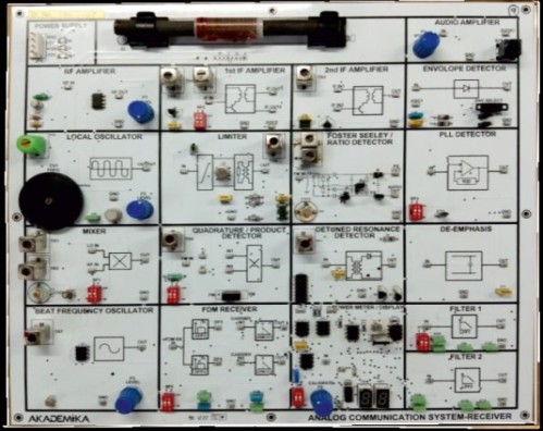
ANALOG COMMUNICATION SYSTEM- RECEIVER
a) RF AMPLIFIER BLOCK
RF Amplifier: 600 KHz to 1650 Khz with adjustable gain
b) LOCAL OSCILLATOR BLOCK
Output signal: Sine wave for local oscillator input
Frequency: 900 KHz to 2.1MHz variable
Amplitude: Adjustable from 0 ~ 2Vp-p
Output Impedance: 50 Ohms
c) MIXER BLOCK
Dual gate MOSFET IN
Inputs: Local oscillator and RF Signal
Output Frequency: 455KHz adjustable
d) IF AMPLIFIER & FILTER BLOCK
1st IF and 2nd IF amplifier
Central frequency: 455KHz
Load impedance: Variable R-L-C
Gain: 32dB with automatic gain control
Filter 1 & Filter 2: Cut off Frequency of 3.4KHz
e) DEMODULATOR BLOCK
Beat Frequency Oscillator
Central Frequency: Adjustable to 457KHz
Amplitude: 0 to 2V variable
Diode Envelope Detector:
Detection of Positive & Negative envelope with variable RC filter DSB
Limiter:
455 KHz central Frequency 1.5V output amplitude
Quadrature / Product Detector:
Operating frequency: Adjustable from 400KHz ~ 500KHz SSB
Foster Seeley / Ratio Detector:
Operating frequency : Adjustable 400KHz ~ 500KHz (SSB)
PLL Detector:
Operating frequency : Adjustable 400KHz ~ 500KHz (SSB)
Detuned Resonance Detector:
Operating frequency : Adjustable 400KHz ~ 500KHz (SSB)
De-emphasis: Time Period with 50usFDM Receiver:
FDM Receiver:
Band Pass Filter: 7 KHz to 11 KHz, Fc = 9 Khz,
Band Pass Filter: 18 KHz to 22 Khz, Fc = 20 KhzPower Meter with Integrator and Dump Circuit:
2 Digit Seven Segment Display with 1 - 15 sec Timer
Input signal Amplitude 0 to 2V
f) RECEPTION via ANTENNA and APPLICATION BLOCK
Antenna: Ferrite Rod & MW coil
Audio Amplifier: Audio Amplifier with headphone and adjustable gain.
g) Switch Fault:
Switch Faults are provided to simulate fault condition in various parts of the circuit.
h) Power Supply:
GND, +5V, + 12V, -12V
Module 1: Linear Modulation
Amplitude Modulation
Frequency Spectrum of AM
Generation of AM signal
Modulation Index of AM
Observed Linearity Curve of AM Modulator
SSB-SC / DBS-SC
AM Demodulation - Envelope and Square Law Demodulation
Phase Discriminator Method
Module 2: Frequency Division Multiplexing
FDM
Module 3: Angle Modulation
Principle of frequency and phase modulation - Relation between FM and PM waves
Frequency deviation & Modulation Index of FM
Bandwidth and spectrum of FM
Module 4: Demodulation of Angle Modulated Signals
FM detectors — slope detectors
Ratio detectors
The Phase Locked Loop
Pre-emphasis and de-emphasis
Module 5: Receivers and Noise in Analog Communication
Super-heterodyne receiver (AM and FM)
Observed Frequency Response of Ceramic Filter
Study of Selectivity & Sensitivity of AM Receiver
Effect of Noise on Analog Systems
Noise Power Spectral Density Measurement
SNR and Noise Figure measurement
Module 6: Filter
Study of Band Pass Filter
Study of Band Reject Filter
Study of High Pass Filter
Study of Low Pass Filter
Study of Matched T Filter
With 35 years of legacy in Technical Education, Akademika extends its expertise to Defence and Skill development, building Innovative, Reliable Training Systems for the next generation of Learners.
Partner with Akademika
Join leading institutions that trust our engineering to Advance Learning and Research.