Technology Labs
FOL-B-P: Fiber Optic Communication Trainer
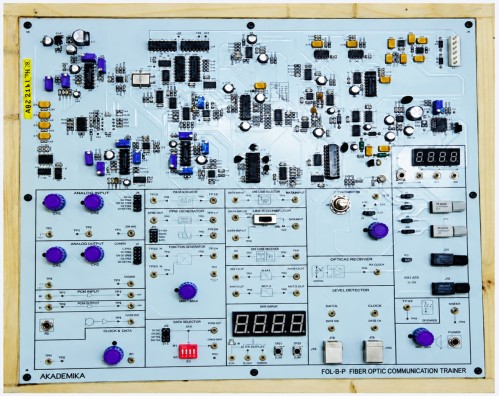
About Product
The FOL-B-P Fiber Optic Communication Trainer is a complete hands-on training system designed to demonstrate key principles of fiber-optic communication, including analog and digital transmission, various modulation techniques, and PC-to-PC data communication. Equipped with dual-wavelength transmitters, multiple detector types, on-board signal generation, and voice/data communication capability, it enables practical experimentation and performance analysis of real-world fiber-optic links.
1) Fiber Optic Transmitter & Receiver : 660/950nm.
2) LED transmitter with PIN photodiode and phototransistor receivers.
3) Analog and digital fiber optic communication.
4) LED/detector characteristics study.
5) BER measurement and PC communication via USB interface.
6) Digital Panel Meter.
7) Switch Faults.
2) LED transmitter with PIN photodiode and phototransistor receivers.
3) Analog and digital fiber optic communication.
4) LED/detector characteristics study.
5) BER measurement and PC communication via USB interface.
6) Digital Panel Meter.
7) Switch Faults.
1) Transmitter : Two fiber optics LED
2) Transmitter 01 : Peak wavelength of emission 660nm red visible (SFH756V)
3) Transmitter 02 : Peak wavelength of emission 950nm (SFH450V)
4) Receiver : Two fiber optic photo detector
5) Receiver 01 : PIN photo diode with responsivity of 0.3 μA (SFH250V)
6) Receiver 02 : Photo Detector with TTL Logic output (SFH551V)
7) On-Board Signals
i) Sine Wave - Frequency : 1Hz ~ 100KHz with selectable frequency range -Amplitude : 0 ~ 4 Vpp
ii) TTL-Square Wave - Frequency : 1Hz ~ 100KHz
8) Carrier Generator
i) Sine Wave - Frequency : 1Hz ~ 100KHz with selectable frequency range - Amplitude : 0 ~ 4 Vpp
9) Modulation techniques
i) Direct intensity modulation
ii) Frequency modulation
iii) Amplitude Modulation
iv) Pulse width modulation (PWM) (with variable clock 4 KHz, 8 KHz, 16 KHz, and 32 KHz)
v) PPM
10) Driver Circuit
i) Analog / digital configuration for 660 nm and 950 nm LED
11) Analog/digital bandwidth
i) 2 MHz / 5MHz
12) Filter circuit - 2 Nos.
i) 4ᵗʰ order Butterworth filters with 3.4 KHz cut-off frequency
13) Port type - USB interface
14) Voice Communication
i) Fiber optic link using Mic with headphones
15) PRBS Generator
16) BER Measurement
17) PC To PC Communication
i) PC to PC communication using 660 nm and 950 nm LED through USB
18) Baud rate - Maximum 115.2 kbps baud
19) Fiber optic cable : Type : Plastic optical cable, step index, multimode
20) Core Refractive
i) Index-n1 : 1.492
ii) Numerical aperture : 0.5
iii) Acceptance angle : 60°
iv) Fiber diameter : 1000 microns
v) Outer diameter : 2.2 mm
vi) Fiber lengths : 1 and 3 Mtr
21) Power supply
i) GND, +5V, –5V, +12V, -12V
1) Setting up a fiber optic analog link.
2) Study of losses in optical fiber : - Measurement of propagation loss and bending loss.
3) Study of characteristics of fiber optic LED and detector.
4) Measurement of numerical aperture.
5) Study of frequency modulation and demodulation using fiber optic link.
6) Setting up a fiber optic digital link.
7) Study of Amplitude Modulation and Demodulation usind fiber optic link.
8) BER Measurement using PRBS data and Error Generator.
9) Detector Characteristics.
10) Study of modulation and demodulation of light source by pulse width modulation (PWM) and pulse position modulation (PPM) techniques.
11) Forming PC to PC communication via USB Interface.
12) Setting up a fiber optic voice link.
13) Study of Digital Panel Meter.
14) Switch faults.
With 35 years of legacy in Technical Education, Akademika extends its expertise to Defence and Skill development, building Innovative, Reliable Training Systems for the next generation of Learners.
Partner with Akademika
Join leading institutions that trust our engineering to Advance Learning and Research.