Technology Labs
FOL-CWDM: Coarse WDM and Bragg Grating Module
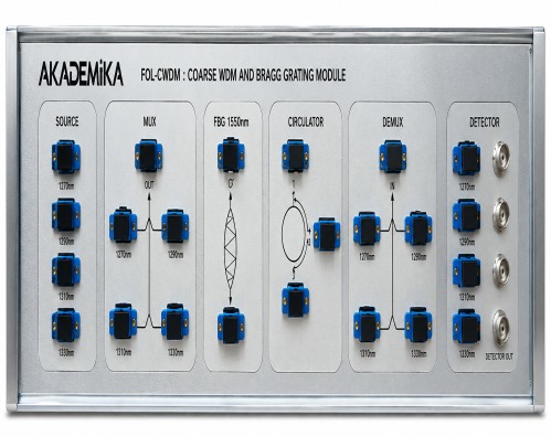
1) Coarse Wavelength Division Multiplexing system covers practical aspect of implementing the design by study of optical component parameters and verifying their performance.
2) De multiplexing of wavelengths is demonstrated along with the recovery of the transmitted signal. Channel addition and deletion (dropping) is implemented using Bragg grating and three port optical circulator.
3) This training system is a bench top model capable of demonstrating CWDM with Add-Drop functionality. This system operates in PC control mode.
CWDM Channels
1) ITU-T have specified range of wavelengths which can be used for CWDM with 20nm spacing between two multiplexed wavelengths.
2) The CWDM channels defined by ITU-T in optical transmission band.
3) CWDM uses 18 channel in the wavelength range 1270~1610nm spaced 20nm (guard Band) apart.
1) 1.25Gbps CWDM Laser Diode Modules at wavelengths of 1510nm, 1530nm, 1550nm, 1570nm
2) In built Isolator
3) Channel Spacing : 20 nm
4) Threshold Current Ith : 10 mA Typical
5) Output Power : @ Ith + 30 mA -> 0.7mW @ ~ 58 mA -> 1.4 mW
6) Operating Voltage : 1.1V Typical
7) Modulation : Digital modulation with maximum modulation frequency 5MHz
DETECTORS
i) 1.5 GHz InGaAs PIN Photo diode Module
ii)) Responsivity : Typical 0.9 A/W in 9/125μm fiber
iii) Spectral Range : 1250nm to 1600nm
iv) Reverse Voltage : 30V max
4-Channel CWDM Mux and Demux
i) Mux combines two or more wavelengths together and send them over a single fiber
ii) De-mux receives the combined wavelengths and separates them
iii) Center Wavelength : 1510nm, 1530nm, 1550nm, 1570nm
iv) Channel Spacing : 20nm
v) Pass band @ 0.5dB : ITU+/- 6.5 nm
vi) Insertion Loss @ MUX / DEMUX Port : <= 2.9 dB
vii) Adjacent Channel Isolation : >= 30 dB
viii) Non Adjacent Channel Isolation : >= 40 dB
ix) Max Optical Power : 300 mW
3- Port Circulator
i) Optical Circulator are micro optic devices and can be made with any number of ports but 3 and 4 port versions are most common.
ii) It comprises three single mode fibers (SMFs), single-fiber ferrules, lenses and a non-reciprocal section using a uniaxial birefringent crystal.
iii) Polarization Independent Optical Circulator
iv) Band : C+L
v) Wavelength Range : 1525nm to 1610nm
vi) Transmission Direction : 1 - >2 , 2 - > 3
vii) Channel Isolation : > 40dB
viii) Insertion Loss : <= 0.9 dB
Fiber Bragg Grating
i) A Fiber Bragg grating (FBG) is a type of distributed Bragg reflector constructed in a short segment of optical fiber that reflects particular wavelength of light and transmits all others.
ii) This is achieved by creating a periodic variation in the refractive index of the fiber core, which generates a wavelength-specific dielectric mirror.
iii) Central Wavelength : 1550
iv) Bandwidth : 10 nm
v) FBG Length : 10 mm
vi) Reflectivity : >90%
Facility for Add-Drop
i) It is possible to ADD-DROP channel using combination of Bragg grating and Circulator.
Software
i) User friendly GUI for monitoring, controlling of CWDM system.
ii) Operating modes support CW mode, VI characteristics mode, Internal & External Modulation.
iii) LASER control allows Supply ON/OFF, wavelength selection and driving current.
iv) Real time signal level monitoring of Photo-detector.
v) Graphical representation : XY plot of VI characteristics and Internal Modulation.
vi) COM Settings : USB 2.0
vii) Operating System : Windows 8 & 10
viii) Interface : USB interface.
ix) Software Interface.
x) VI Characteristics of each LASER are displayed on graph.
xi) Four LASER outputs can be seen simultaneously and their input voltage is manually controlled using slider in software.
ACCESSORIES
1) Shielded USB A-B cable : 01 No.
2) Power Cable : 01 No.
3) SC/PC –SC/PC Single Mode Fiber Optic Patch Chords : 12 No.
4) BNC to BNC coaxial cable : 04 No.
5) Software on Pendrive : 01 No.
6) FTDI Drivers included.
7) Experimental Manual : 01 No.
Component Characteristics
1) Diode LASER characterization
2) MUX & DEMUX characterization
3) Optical circulator characterization
4) Bragg Grating characterization
Optical VCommunication system
1) 4 Channel CWDM by internal & external modulation
2) Add/Drop using Circulator & Bragg Grating
1) Diode LASER characterization
2) MUX & DEMUX characterization
3) Optical circulator characterization
4) Bragg Grating characterization
Optical VCommunication system
1) 4 Channel CWDM by internal & external modulation
2) Add/Drop using Circulator & Bragg Grating
With 35 years of legacy in Technical Education, Akademika extends its expertise to Defence and Skill development, building Innovative, Reliable Training Systems for the next generation of Learners.
Partner with Akademika
Join leading institutions that trust our engineering to Advance Learning and Research.