Technology Labs
RFL-AMS-A: 4 GHz Motorized Antenna Trainer
About Product
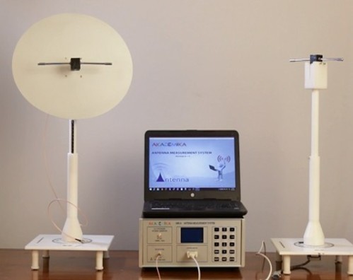
The RFL-AMS-A is a fully motorized antenna measurement system supporting UHF to S-band up to 4 GHz, enabling real-time radiation pattern plotting, gain evaluation, and polarization studies. With 22 standard antennas and LabVIEW-based analysis software, it delivers hands-on learning for wire, microstrip, array, reflector, and aperture antenna design.
Single training system to teach all types of antenna measurement
Covers UHF, L, S and ISM Bands
Software controlled PLL Synthesized Source and Detector working up to 4GHz with high dynamic range of power transmission
Graphical LCD Display with numeric keypad to monitor and navigate the experiments.
Facility for testing user defined antenna.
Customized selection of antenna from the list as per syllabus requirement
Practical approach for Microstrip Antenna designs
Non-conductive and non-magnetic Transmitter and Receiver stand
Lab View Based Radiation pattern plotting software
Stepper motor controlled receiver stand.
Antenna Measurement System
RF Source
Source types : PLL Synthesized with integratedVCO
Frequency range : 100MHz to 4GHz
Frequency resolutions : 1MHz
Transmitted power min : -50dBm
Transmittedpower max : +5dBm
Impedance: 50 Ohms / SMARF Detector
Detector type : Logarithmic detector
Frequency range : 1MHz to 8GHz
Resolution: 0.1dB
Dynamic range : 65dB (±3dB)
Impedance: 50 Ohms /SMA
Representationof RF level : dBmDisplay
128x64 Graphic LCD Display with backlight
Keypad
15 Key Membrane Keypad for user entry.
Stepper motor controller
1.8 Degree and 5.4 Degree resolutions
List of Standard 22 Antenna Supplied with the setup
Wire Antenna
Monopole Plane base ground
Dipole (2nos.)
Yagi
Folded Dipole
Vee Dipole
Rectangular Loop
HelicalMicrostrip Antenna
Planar Dipole
Planar Monopole
CMSA
TMSA
2X1ARRAY
Annular ring
Chip Antenna
RMSA
RMSA-Circular PolarizedAperture Antenna
E-Horn
Open ended Waveguide RectangularArray Antenna
Broadside Array
Collinear ArrayReflector Antenna
Corner reflector
SOFTWARE
Radiation pattern plotting and analysis software suitable for windows environment.
Antenna Positioner
The Transmitter and Receiver Antenna stand is made of special material which isinhert to EM
Frequency and it has engraved height and angle scale on it. It has facility to adjust theheight and level.
Universal plug and fix Antenna mounts are provided to hold the antenna assembly invertical and horizontal orientation for co and cross polarization.
Measure the variation of field strength /inverse square law
Prove the reciprocity theorem of antenna
Plot Radiation pattern of all Wired Antenna.
Plot the Radiation pattern of all Planar (Microstrip) Antenna
Plot Radiation pattern of all Array Antenna
Plot Radiation pattern of all Reflector Antenna.
Plot Radiation pattern of all Aperture Antenna.
Measure co-polarization ,cross polarization.
Measurement circularly polarized antennas.
Measurement of Front to back (F/B) ratio of yagi-uda antenna
Measurement of 3 dB beamwidth of horn antenna.
Side lobe level measurement.
Comparative study of different antenna type and its radiation pattern.
Additional Experiments Using Vector Network Analyser (VNA-3000)
Return Loss and VSWR measurement of antennas with broadband freq range.
Bandwidth analysis of different antennas.
Comparative study of different antenna.
Parameters like impedance, bandwidth and VSWR.
Finding operating frequency of an antennas.
Phase measurement of antennas.
Experiments Using Spectrum Analyser (SA3600TG)
Gain measurement of antennas.
Measure the variation of received power vs distance.
With 35 years of legacy in Technical Education, Akademika extends its expertise to Defence and Skill development, building Innovative, Reliable Training Systems for the next generation of Learners.
Partner with Akademika
Join leading institutions that trust our engineering to Advance Learning and Research.