Technology Labs
RFL-RFT: RF Circuit Trainer
About Product
The RFL-RFT is a complete RF and microwave learning platform supporting up to 2 GHz, designed for practical experimentation with microstrip transmission lines, impedance matching networks, and active RF components. It enables performance characterization of amplifiers, filters, and oscillators, helping students master real-world RF circuit behavior
Frequency Range up to 2 GHz
Dedicated Boards for Active and Passive Microstrip components
Analysis of Discontinuities in Microwave Circuits
Analysis of Impedance Matching Networks
Analysis of LNA and PLL
Analysis of Lumped Filters characterization
Analysis of BJT and Power Amplifiers
Good Power handling capacity
Gold plated PCB
Power Supply to drive Active Devices
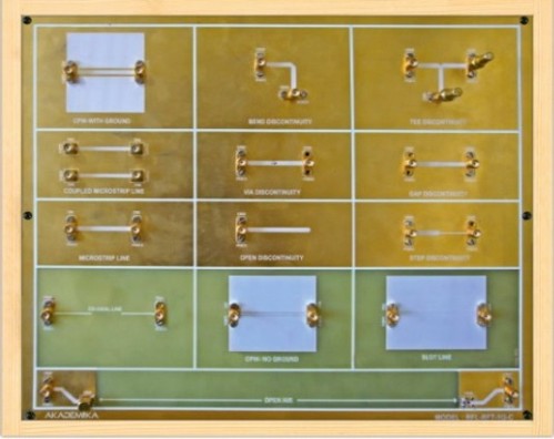
TRANSMISSION CHANNEL & MICROSTRIP DISCONTINUITIES
Open air transmission
Frequency: 0.9GHz to 3GH
Power : 0dBm to -20dB
Load : Matched AntennaCo-axial cable transmission
Frequency: 0.1GHz to 3GHz
Power : 0dBm to -20dBm
Load : Open, shortMicrostrip transmission line
Frequency: 0.9GHz to 3GHz
Power : 0dBm to 20dB
Load : Open, shortCPW transmission line
Frequency: 0.9GHz to 3GHz
Power : 0dBm to -20dB
Load : Open, shortSlot line
Frequency: 0.9GHz to 3GHz
Power : 0dBm to -20dB
Load : Open, shortCPW transmission line with ground
Frequency: 0.9GHz to 3GHz
Power : 0dBm to -20dB
Load : Open, shortCoupled line microstrip transmission line
Frequency: 0.9GHz to 3GHz
Power : 0dBm to -20dB
Load : Balanced loadOpen discontinuity
Frequency: 0.9GHz to 3 GHz
Power : 0dBm to -20dBShort discontinuity
Frequency: 0.9GHz to 1.3GHz
Power : 0dBm to -20dBGAP discontinuity
Frequency: o 0.9GHzto 1.3GHz
Power : 0dBmto -20dB
Load : MatchedBend discontinuity
Frequency: 0.9GHzto 1.3GHz
Power : 0dBm to -20dBStep discontinuity
Frequency: 0.9GHz to 1.3GHz
Power : 0dBm to -20dBm
Load : MatchedFrequency: 0.9GHz to 1.3GHz
Power : 0dBm to -20dBTee discontinuity
Frequency: 0.9GHz to 1.3GHz
Load : MatchedRF CIRCUIT S & MATCHING ARCHITECTURE
RF Lump Element
Frequency: 0.3GHz to 1GHz
Type : Capacitive, Inductive
Load : MatchedHigh frequency effect on Lump Element
Frequency: 0.001GHz to 3GHz
Power : 0dBm to -20dBmInductive Resonance Circuit
Frequency: 0.3GHz to 1GHz
Power : 0dBm to -20dB
Load : Matched, ResistiveCapacitive Resonance Circuit
Frequency: 0.3GHz to 1GHz
Power : 0dBm to -20dB
Load : Matched, ResistiveRLC Resonance Circuit
Frequency: 0.3GHz to 1GHz
Power : 0dBm to -20dB
Load : Matched, ResistiveTunable Resonance Circuit
Frequency : 0.3GHz to 1GHz
Power : 0dBm to -20dB
Load : Variable loadBALUN
Frequency: 0.3GHz to 3 GHz
Power : 0dBm to -20dB
Load : Variable loadDC Bias TEE
Frequency: 0.3GHz to 1.3 GHz
Power : 0dBm
Isolation: 25dBMicrostrip Bias TEE
Frequency: 0.7GHz to 1.3 GHz
Power : 0dBm to -20dB
Load : Matched loadSingle stub matching
Frequency: 0.8GHz to 1.1 GHz
Load : Variable loadQuarter wave transformer
Frequency: 0.8GHz to 1.1 GHz
Load : Variable loadBinomial Quarter transformer
Frequency: 0.8GHz to 1.1 GHz
Load : Variable loadL Matching for resistive load
Frequency: 0.85 GHz to 1.1GHz
Load : Resistive loadL Matching for complex load
Frequency: 0.85 GHz to 1.1 GHz
Load : Complex loadT Matching
Frequency: 0.85 GHz to 1.1 GHz
Load : High load impedance (fixed)PI Matching
Frequency: 0.85 GHz to 1.1 GHz
Load : low load impedance (fixed)RF ACTIVE COMPONENT& ITS APPLICATION CIRCUITS
RF BJT Amplifier
Frequency Range : 0.3GHz to 0.8GHz
GainS21 : > 10dB
Reverse Isolation : < -15dBLow Noise Amplifier
Frequency Range : 0.3GHz to 0.8GHz
Gain : > 10dB
Noise Figure (NF) : < 1.5dBRF Power Amplifier
Frequency Range : 0.3GHz to 1GHz
Gain : > 12dBm
Maximum Output Power : 30dBmRF MOSFET Amplifier
Frequency Range : 0.1GHz to 0.5GHz
GainS21 : > 10dB
Reverse Isolation : < -15dBRF Gain Equalizer
Frequency : 0.4GHz to 0.8GHz
Insertion Loss : < -3dB
Load condition : MatchedRF LC Oscillator
Frequency : 30MHz (±25MHz)
Power Level : > -30dBmPhase Locked Loop
Input Frequency : 500KHz to 5MHz
VCO Locked Freq : 1.3MHz (± 500KHz)RF Frequency Multiplier
Input Frequency Range : 10 to 500MHz
Output Frequency Range : 20 to 1000MHz
Impedance : 50 ohmLumped LPF Filter
CutFrequency : 450MHz ( 3dBm cut off ± 50MHz)
Filterorder : 7
Insertion Loss : < -2dBm
ReturnLoss : < -10dBmLumped BPF Filter
Center Frequency : 350MHz (± 70MHz)
Filter order : 5
Bandwidth : ~ 150MHz @ 3dBmLumped BPF Filter
Center Frequency : 350MHz (± 70MHz)
Filterorder : 5
Bandwidth : ~ 150MHz @ 3dBmLumped HPF Filter
CutFrequency : 450MHz ( 3dBmcut off ± 50MHz)
Filterorder : 7
Insertion Loss : < -2dB
ReturnLoss : < -10dBPower Supply
+24V,+12V, +5V, GND to drive the Active Devices
Measurement of Insertion loss S21 for different devices.
Study of Load condition over transmission line channel.
Measurement of frequency BW response.
Study Z parameter of stub matching circuits.
Study and calculation of Smith chart over a wide band.
Measurement of S11 and VSWR for different devices.
Measurement of Q Factor for different devices.
Measurement of Resonance over Bandwidth.
Measurement of transmission and reflection Characteristic of lumped LPF,HPF and BPF filters
Study network analysis of various RF Active circuits like BJT, MOSFET and LNA Amplifiers.
Measurement of Gain Flatness.
Study of RF Gain equalizer circuit and its measurement.
Study of RF LC Oscillator.
Study RF Frequency Multiplier Circuits.
Study of Phase Locked Loop Circuits
With 35 years of legacy in Technical Education, Akademika extends its expertise to Defence and Skill development, building Innovative, Reliable Training Systems for the next generation of Learners.
Partner with Akademika
Join leading institutions that trust our engineering to Advance Learning and Research.