Technology Labs
BEL-ADT: Analog and Digital Trainer
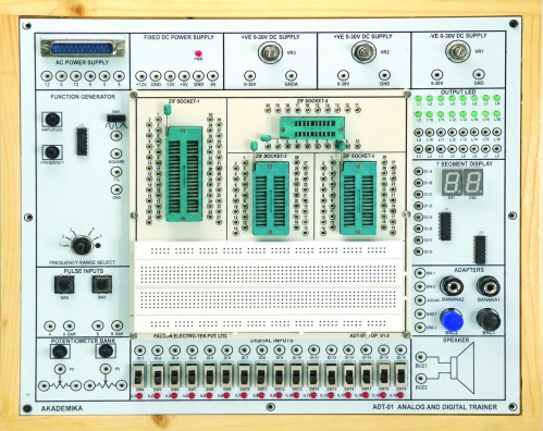
1) Combines all essential functions of analog and digital experiment with removable breadboard, includes DC power supply, function generator, two pulse switches, 8 Ω 0.5W speaker etc.
1) Fixed DC output power supply : ±5V, ±12V@500mA.
2) Dual Variable DC output power supply : 0~30V, 0~-30V@500mA.
3) AC power supply : 5~0~5VAC, 12~0~12VAC.
4) Potentiometer : 1K Ω, 10KΩ
Function generator
1) Frequency range : 1Hz~10Hz
10Hz~100Hz
100Hz~1KHz
1KHz~10KHz
10KHz~100KHz
Amplitude
1) Sine wave output : 0~6Vpp variable@1Hz ~1MHz in step of 5
2) Triangle wave output : 0~6Vpp variable@1Hz ~800KHz in step of 5
3) Square wave output : 0~5Vpp variable@1Hz ~ 800KHz in step of 5
4) TTL mode output : 5V@1Hz~1MHz in step of 5
5) Two digits of 7 segment LED display
6) Two pulse switches : Push buttons to generate inverting and non inverting pulses supported with de-bounce elimination
7) Data Switches : Toggle switches and corresponding output point. When switch is set at “Down” position, the output is ‘LO’ level, contrarily it is to be 'High' level while setting at “Up” position.
8) Speaker : 8 Ω 0.5W to be used as Load.
9) Four channel adapter : The two banana sockets and BNC jacks suitable for the trainer to be connected with peripherals
10) Sixteen bit LED display : Red LEDs separate input terminals. The LED will be lighted up when input is at “High level” and it will be turned OFF when it is at “No Input” or at “Low level”
11) ZIF Sockets: 40 pin-1No , 28 pin-2 Nos, 20 pin-1No
* It is an open-board system, and any basic electronics experiment can be performed on it.
With 35 years of legacy in Technical Education, Akademika extends its expertise to Defence and Skill development, building Innovative, Reliable Training Systems for the next generation of Learners.
Partner with Akademika
Join leading institutions that trust our engineering to Advance Learning and Research.