Technology Labs
BEL-COT: Discrete Components Trainer
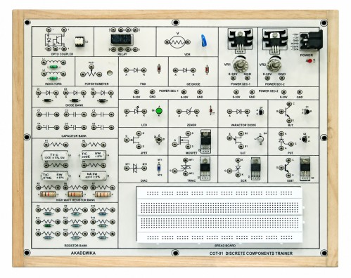
About Product
Interactive hardware for analyzing semiconductor devices including Zener, LED, Varactor, JFET, MOSFET, DIAC, TRIAC, SCR, IGBT & Optocoupler. Enables practical study of clipping, clamping, rectification, tuning, power devices, and basic circuit laws a must-have for device characterization labs.
1) Single board system, capable of covering over 20 Experiments.
2) Covers basic semiconductor devices such as Diodes, BJT, FET, MOSFET, UJT, PUT, DIAC, TRIAC, SCR, IGBT.
3) IEEE symbol of all components provided on the PCB.
4) All Components are visible clearly on the top of the PCB.
5) Mobile based Interactive e-Manual.
2) Covers basic semiconductor devices such as Diodes, BJT, FET, MOSFET, UJT, PUT, DIAC, TRIAC, SCR, IGBT.
3) IEEE symbol of all components provided on the PCB.
4) All Components are visible clearly on the top of the PCB.
5) Mobile based Interactive e-Manual.
1) On-board resources such as Resistor, Capacitor, Diode and Potentiometer banks of different values should be available.
2) On-board Relay and Opto-coupler.
3) On-board variable regulated dual power supply (500mA)
range from 0V to 30V.
4) Resistor Bank (16 resistors)
Range from 100E to 620Ω for 5 watt
Range From 1KΩ to 10KΩ for 2 watt
Range from 100Ω to 200KΩ for ¼ watt
5) Capacitor Bank (6 capacitors) : Range from 0.1µF to 100 µF
6) Inductor (1mH)
7) Potentiometer(10K)
8) Diode (1N4007)
9) Good quality Breadboard (175mmX63mm) provided
10) Semiconductor Device Range : Germanium Diode(1N60)
11) Fast Switching Diode(1N4148)
12) Zener Diode(5.1V)
13) Light Emitting Diode (GREEN LED 5mm)
14) Bipolar Transistor (BC547)
15) Uni-Junction Transistor 2N2646 (UJT-N channel)
16) Field Effect Transistor (JFET BF245)
17) MOSFET(IRF-Z44N)
18) DIAC(DB3)
19) TRIAC (BT136)
20) IGBT (IRG4BC30S)
21) Silicon Controlled Rectifier (SCR TYN604)
22) Voltage Dependent Resistor(VDR)
23) Opto-Coupler (MCT2E)
24) Varactor Diode (MV209)
25) Relay (2A0214)
1) Study the working of Resistors, Capacitors, Inductors, Potentiometer, Relay
2) Study the frequency response working of Opto-Coupler
3) Characteristics study of Si-Diode, FSD-Diode, Ge-Diode, Zener Diode, LED, Varactor Diode, VDR
4) Characteristics study of BJT in CE, CB and CC mode
5) Characteristics study of JFET, MOSFET, UJT, PUT, DIAC, TRIAC, SCR, IGBT
6) To find the value of unknown resistance
7) Study of Ohm's law
8) Study of Kirchoff's voltage and current law
9) Study of voltage and current divider rule
10) Diode capacitance variation
11) Diode clipper and clamper
12) Logic gate using diode
13) Voltage multiplier
14) Zener diode regulator
15) Power supply filter
16) Effect of frequency on R, L, C
17) RC integrator and differentiator
18) RC filters
19) Time constant of a series RC circuit
20) Transient response of series RC
21) Transient response of series RL
22) RLC series and parallel resonance
With 35 years of legacy in Technical Education, Akademika extends its expertise to Defence and Skill development, building Innovative, Reliable Training Systems for the next generation of Learners.
Partner with Akademika
Join leading institutions that trust our engineering to Advance Learning and Research.