Technology Labs
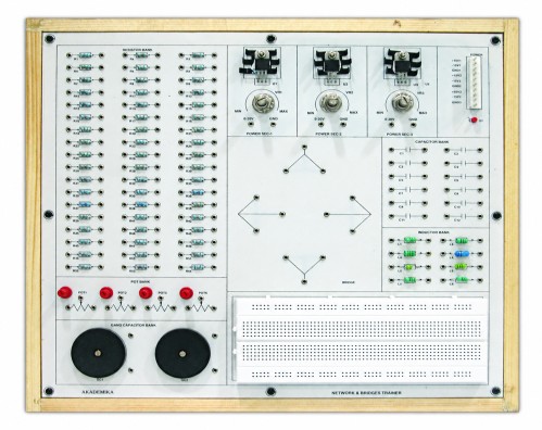
BEL-NBT: Network And Bridges Trainer
About Product
A complete trainer that enables students to verify core electrical theorems and characterize AC bridges with built-in R, L, C banks and a solder-less proto area. Covers Superposition, Thevenin, Norton, Maximum Power Transfer, Reciprocity, KCL/KVL, and advanced bridges including Hay’s, Schering, Anderson, Owen’s and LC resonance.
1) Single board system, capable of covering multiple Experiments on basic electrical networks and bridge circuits.
2) IEEE symbol of all components provided on the PCB.
3) All Components are visible clearly on the top of the PCB.
4) Mobile based Interactive e-Manual.
2) IEEE symbol of all components provided on the PCB.
3) All Components are visible clearly on the top of the PCB.
4) Mobile based Interactive e-Manual.
1) Three variable regulated DC power supplies of 0-20 V with helical potentiometer control.
2) Fixed supply sections shall be available as +25V1, -12V1, GND1; +25V2, -12V2, GND2; +25V3, -12V3, GND3
3) On-board resistor bank, capacitor bank, gang capacitors, potentiometers and inductor bank.
4) Resistor Bank (54 resistors)
Range from 4.7Ω to 150KΩ for ¼ watt
5) Capacitor Bank (12 capacitors)
Range from 33 pF to 47 µF
6) Inductor Bank (8 inductors)
Range from 1 mH to 10 µH
7) Potentiometer Bank (4 Potentiometers)
Range from 1K to 100K
8) Gang capacitors shall be provided for variable capacitance adjustment.
(PF and µF)
9) Breadboard
1) Superposition theorem
2) Thevenin's theorem
3) Norton's theorem
4) Maximum power transfer theorem
5) Reciprocity theorem
6) Two port network parameter (Z and Y parameter)
7) To find unknown resistance using Wheatstone bridge
8) To find unknown capacitance using De'saunty's bridge
9) To find unknown low resistance using Kelvin's bridge
10) Maxwell's theorem
11) Verification of Ohm's law
12) Verification of Kirchoff's law (KCL and KVL)
13) Verification of Mesh current analysis
14) Verification of Nodal voltage analysis
15) Verification of source transformation
16) To verify compensation theorem
17) Study of resistor ladder network
18) To verify Millman's Theorem Assignments
19) Hay's bridge
20) Schering bridge
21) Andersen bridge
22) Owne's bridge
23) LC resonance
With 35 years of legacy in Technical Education, Akademika extends its expertise to Defence and Skill development, building Innovative, Reliable Training Systems for the next generation of Learners.
Partner with Akademika
Join leading institutions that trust our engineering to Advance Learning and Research.