Technology Labs
BEL-PET: Power Electronics Trainer
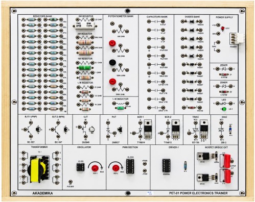
1) Single board system, capable of covering different power electronics experiments
2) IEEE symbol of all components provided on the PCB.
3) All Components visible clearly on the top of the PCB.
4) Mobile based Interactive e-Manual
2) IEEE symbol of all components provided on the PCB.
3) All Components visible clearly on the top of the PCB.
4) Mobile based Interactive e-Manual
1) Power Supply: 30V AC & 12V DCOn-board passive & active components
2) THYRISTORS (SCR (TYN604), TRIAC(BT-136), DIAC(DB-3), UJT(2N2646), PUT (2N6027), MOSFET(IRF-Z44N), BJT PNP(BC-557), BJT NPN (BC-547)
3) Oscillator (IC 555) with a tuning pot should be provided
4) 12 TAP Transformer with different number of windings
5) Resistor bank (34 Resistors)
Range from : 10Ω to 910 KΩ (¼ watt)
6) Different wattage Resistors (8 Resistors)
Range from : 0.1Ω to 1M Ω
Range from : 1/2 W to 5 W
7) Capacitor Bank (11 capacitors)
Range from : 0.01µF to 220n
FInductor ½W : 100µH
8) Potentiometer bank (4 pots)
Range from : 100Ω to 500KΩ
9) Diode Bank (11 diodes)
1N4007_5 nos.
1N5819_5 nos.
1N4148_1 nos.
1) Using SCRStudy of single-phase half wave control
2) Study of full wave controlled rectifier
3) Study of single-phase DC to AC inverter
4) AC power flasher using SCR
5) Lamp Dimmer Circuit using DIAC-TRIAC
6) DC to DC converter (dual)Low voltage lamp flasher using PUT and SCR
7) LED flasher using SCR and UJT
8) Study SCR triggering using Ic555
9) SCR time delay relay
With 35 years of legacy in Technical Education, Akademika extends its expertise to Defence and Skill development, building Innovative, Reliable Training Systems for the next generation of Learners.
Partner with Akademika
Join leading institutions that trust our engineering to Advance Learning and Research.