Technology Labs
FOL-PHYSICS: Physics Of Fiber Optic Lab
About Product
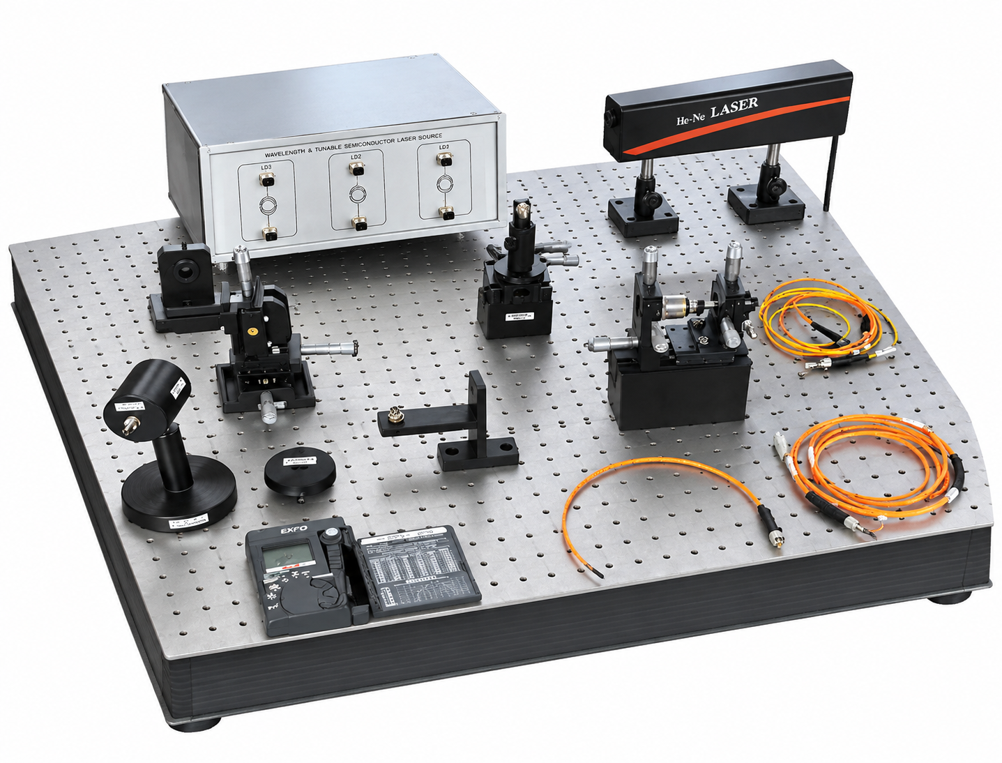
The FOL-PHYSICS: Physics of Fiber Optic Lab is a complete educational platform designed to explore fundamental optical fiber physics, including waveguide construction, mode propagation, and optical coupling principles. Equipped with a He-Ne laser source, precision fiber couplers, power measurement instruments, optical breadboard, and multiple single-mode and multimode fibers, the system enables a wide range of fiber-optic characterization experiments.
1)This laboratory is designed to study the physics of fiber optics.
2) It deals with the study of various important characteristics of optical fiber cable like numerical aperture, V number, attenuation, coupling loss and mode field diameter.
2) It deals with the study of various important characteristics of optical fiber cable like numerical aperture, V number, attenuation, coupling loss and mode field diameter.
1) Laser
i) Source Type : He-Ne Laser
ii) Wavelength : 632.8nm
iii) Light : Red Visible
iv) O/P Power : 2mW
v) Complete system with power supply
2) Laser to fiber coupler
i) Laser to fiber coupler with Lens adjustment facility to adjust beam into core of fiber
ii) Coupling Efficiency : >70% for SM fibers > 90% for MM fibers
iii) Operation Wavelength : 180 to 2000nm
iv) Power Handling Capacity : >1watt
3) Laser power meter
i) Digital display : 4039 full scale
ii) Bar graph display: 41-segment display
iii) Power Measurement : 0.01μW ~ 40.39mW
iv) Resolution : 1nW
v) Power Supply : LR44 1.5 V x 2
vi) Over Load Indication : Displays “OL”
vii) Operation Wavelength : 400 ~ 1100 nm
viii) Calibrated to 633nm
4) Optical Patchcord ST-ST
i) Single Mode : 9/125 um 1mtr.
ii) Multi Mode : 62.5/ 125 um 1 mtr.
iii) Multi Mode Fiber Pigtail : 62.5/125um 1 mtr.
iv) Multi Mode : 100/140um 1mtr.
5) Spool
i) 3 in 1 Multi Mode Spool (100m, 500m, 1000m)
Measurements & Method
1) Measurement of Coupling Loss
i) In order to achieve maximum coupling efficiency, the fiber core diameter has to be bigger than the spot diameter.
ii) Another factor which determines the coupling efficiency is the matching of fiber numerical aperture to numerical aperture of the focused rays.
iii) The size of the single mode fiber is very small, around 4-9 microns.
iv) For minimum coupling loss couple alignment should be proper and LASER beam characteristics should be matched properly.
2) Measurement of Numerical Aperture
i) Numerical Aperture is range of acceptance angles rotated around axis, where light can be coupled into a waveguide such as the core of an optical fiber.
ii) The blue cone is known as the cone of acceptance.
iii) Light waves within the acceptance cone can be collected in a small area which can then be sent into the optical fiber.
iv) Numerical aperture is measure of light gathering capacity of optical fiber. Light outside the acceptance cone cannot be coupled to onto optical fiber.It can be calculated quantitatively using formula NA=nSinØ
3) Measurement of Mode Field Diameter of an Optical Fiber
i) The mode field diameter (MFD) represents a "measure of the transverse extent of the electromagnetic field intensity of a mode of light in a fiber cross section".
ii) In optical fiber, this typically is larger than the fiber core, since a portion of the light propagates through the cladding.
iii) MFD is determined using a Gaussian approximation of the intensity distribution with the MFD defined as the width of the curve at the 1/e² power level.
4) Measurement of Attenuation of a Optical Fiber by Cutback Method
i) The cutback method is used for measuring the total attenuation of an optical fibre.
ii) The cutback method begins by measuring the output power Py of the test fibre of known length 'L'. Without disturbing the input conditions, the test fibre is cut back to a shorter length.
iii) The output power Px of the short test fiber is then measured and the fibre attenuation 'A' and the attenuation coefficient 'a' are calculated
5) Mode Observation
i) Light propagates through the fiber core only at specific angles within the N.A. cone.
ii) The acceptance cone consists of discrete annular conical ray paths, not a continuous solid cone.
iii) In optical fiber, modes are different patterns of light intensity distribution around the core axis
ACCESSORIES
i) Optical Bread Board : 01 No
ii) X-Y-Z Translation Stage : 01 No
iii) He-Ne Laser Source : 01 No
iv) Rotary Stage : 01 No Laser
v) Power Meter : 01 No
vi) Laser to Fiber Coupler : 01 No
vii) He-Ne Laser Height Adjustable Stand : 02 No
viii) Laser to Fiber Coupler Holder : 01 No
ix) Laser to Fiber Coupler Holder Base : 01 No
x) Rotary Stage Block : 01 No
xi) Rotary Fiber Holder With Receptacle : 01 No
xii) Fiber Coupler with V-Groove Fiber Holder : 01 No
xiii) Fiber Coupler with V-Groove Fiber Holder Block : 01 No
xiv) Photo Detector Holder : 01 No
xv) Photo Detector Cap With Receptacle : 01 No
xvi) Photo Detector Cap With Knife-edge Slit : 01 No
xvii) Fiber Holder Stand : 01 No
(a) Fiber Holder Stand Base : 01 No
(b) Fiber Holder Stand Horizontal Plate (with Receptacle) : 01 No
(c) Fiber Holder Stand Vertical Plate : 01 No
xviii) Photo Detector Holder Adjustable Stand : 01 No
Fiber Cable
i) 9/125 um SM ST-ST Patch Cord, 1 Meter : 01 No
ii) 62.5/125 um MM ST-ST Patch Cord, 1 Meter : 01 No
iii) 62.5/125 um MM Pigtail, 1 Meter : 01 No
iv) 100/140 um MM ST-ST Patch Cord, 1 Meter : 01 No
v) 62.5/125 um MM ST-SC Patch Cord, 1 Meter : 02 No
vi) 3-in-1 MM Spool (100m, 500m, 1000m) : 01 No
1) Mode Observation
2) Measurement of coupling loss of an optical fiber
3) Measurement of numerical aperture and calculation of V-Number of an end prepared optical fiber
4) Measurement of attenuation of an optical fiber by cut-back method
5) Calculation and measurement of far field pattern of an optical fiber as a function of angle to find the Mode Field Diamter of the Fiber
With 35 years of legacy in Technical Education, Akademika extends its expertise to Defence and Skill development, building Innovative, Reliable Training Systems for the next generation of Learners.
Partner with Akademika
Join leading institutions that trust our engineering to Advance Learning and Research.