Technology Labs
RFL-MCT: 3GHz Microstrip Component Training System
About Product
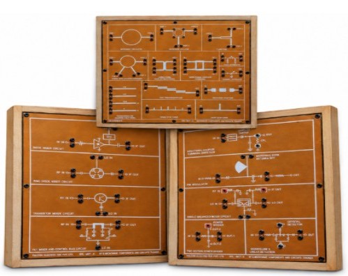
The RFL-MCT is a robust microstrip RF trainer supporting up to 3 GHz, designed for practical study of active and passive components, including MMIC amplifiers, VCOs, mixers, filters, couplers, and RF switches. It enables complete RF subsystem design with real-time S-parameter and performance characterization for hands-on microwave engineering learning.
1) The RFL-MCT-A-3G kit is designed to introduce the fundamentals of microstrip line technology with emphasis on Basic and Advance Microstrip Active and Passive Circuit design concepts. The design frequency range is up to 3GHz. The trainer kit contains Gold plated components in a accurate, robust and integrated board platform.
ACTIVE COMPONENT BOARD 1 · SOURCE
1) MMIC Amplifier
i) Frequency - 100 MHz to 3 GHz
ii) Noise Figure - 2.9 dB @ 3 GHz
iii) Reverse Isolation - 20 dB (typical)
2) VCO
i) Frequency - 1300 MHz – 3 GHz
ii) Power Output - 8 dBm (typical)
iii) Tuning Voltage - 0.5 V to 10 V
3) Frequency Mixer
i) RF / LO Frequency - 1300 MHz to 3 GHz
ii) LO Power IN - +7 dBm
iii) IF Out - DC to 1000 MHz
iv) Conversion Loss - 6.3 dB (typical)
v) Isolation - 20 dB (typical)
PASSIVE COMPONENT BOARD 2 · MICROSTRIP FILTERS
1) LPF
i) Frequency Range - 100 MHz to 2 GHz (3 dB cut-off +/- 50 MHz)
ii) Insertion Loss - < 1.5 dB
2) HPF
i) Frequency Range - 1.9 GHz (3 dB cut-off +/- 50 MHz)
ii) Insertion Loss - < 1.5 dB
3) BPF
i) Center Frequency - 2 GHz (+/- 50 MHz)
ii) Bandwidth - ~ 300 MHz @ 3 dB · ~ 800 MHz @ 30 dB
4) BSF
i) Center Frequency - 1.8 GHz (+/- 50 MHz)
ii) Bandwidth - ~ 850 MHz @ 3 dB · ~ 400 MHz @ 25 dB
5) Attenuators
i) Tee Attenuator - 5 dB
ii) PI Attenuator - 10 dB
COUPLERS
1) Coupled Line Directional Coupler
i) Center Frequency 2 GHz (+/- 50 MHz)
ii) Coupling 13 dB
iii) Isolation > 20 dB
2) Branchline Coupler
i) Center Frequency 2.45 GHz (+/- 50 MHz)
ii) Isolation > 25 dB
3) Rat Race Coupler
i) Center Frequency 2.45 GHz (+/- 50 MHz)
ii) Isolation > 25 dB
4) Ring Resonator
i) Center Frequency 2.45 GHz (+/- 10 MHz)
ii) Bandwidth 60 MHz
5) Circulator
i) Frequency 2.5 GHz
6) Power Divider
i) Frequency 2 GHz to 2.5 GHz
ii) Isolation > 20 dB
7) TRANSMISSION LINE TERMINATIONS / LOADS
i)OPEN Termination
ii) SHORT Termination
iii) MATCHED Load
iv) MISMATCHED Load
ACTIVE COMPONENT BOARD 3 · DETECTOR
1) Pin Diode Switch
i) SPST Switch Freq - 300 MHz to 1 GHz
ii) SPDT Switch Freq - 1 GHz to 2 GHz
iii) Insertion loss - < 3 dB
2) Schottky Diode Detector
i) Frequency 2.2 GHz to 2.5 GHz
ii) Input power -30 dBm to 10 dBm
3) Pin diode variable Attenuator
i) Frequency - 1.5 GHz to 2.5 GHz
ii) Attenuation range - 7 dB to 17 dB
iii) Variable Voltage - 0V to +5V
1) Directional coupler
i) Insertion loss of through port [SA ✓ · VNA ✓]
ii) Coupled & Isolation port magnitude [SA ✓ · VNA ✓]
iii) Return loss characteristics [SA ✗* · VNA ✓]
iv) Smith chart, impedance [SA ✗ · VNA ✓]
v) Phase characteristics of Through, Coupled & Isolation port [SA ✗ · VNA ✓]
2) Circulator / isolator
i) Transmission/insertion loss characteristics [SA ✓ ·VNA ✓]
ii) Return loss characteristics [SA ✗* · VNA ✓]
iii) Phase characteristic [SA ✗ · VNA ✓]
3) Ring resonator
i) Transmission characteristics [SA ✓ · VNA ✓]
ii) Bandwidth and quality factor [SA ✓ · VNA ✓]
4) Microstrip 3dB power divider
i) Power division characteristics [SA ✓ · VNA ✓]
ii) Isolation characteristics [SA ✓ · VNA ✓]
iii) Return loss characteristics [SA ✗* · VNA ✓]
iv) Amplitude balance [SA ✓ · VNA ✓]
v) Phase balance [SA ✗ · VNA ✓]
5) Microstrip filters
i) Insertion loss characteristics, 3dB and 15dB bandwidth [SA ✓ · VNA ✓]
ii) Filter slope, roll-off, bandwidth [SA ✓ · VNA ✓]
iii) Return loss characteristics [SA ✗* · VNA ✓]
iv) Phase and group delay [SA ✗ · VNA ✓]
6) Fixed attenuator
i) Return loss characteristics [SA ✗ · VNA ✓]
ii) Insertion loss/attenuation level characteristics [SA ✓ · VNA ✓]
7) MMIC amplifier
i) Gain & Reverse Isolation [SA ✓ · VNA ✓]
ii) Input / output return loss [SA ✗ · VNA ✓]
iii) 1 dB compression point [SA ✓** · VNA ✓**]
iv) Phase characteristics [SA ✗ · VNA ✓]
8) Active phase shifter
i) Return & Insertion loss characteristics [SA ✗ · VNA ✓]
ii) Tuning voltage Vs Phase characteristics [SA ✗ · VNA ✓]
iii) Total phase variance (Δφ) [SA ✗ · VNA ✓]
9) Frequency mixer
i) Measurement of IF [SA ✓ · VNA ✗]
ii) Return loss BW [SA ✗ · VNA ✗]
iii) IF conversion loss [SA ✓ · VNA ✗]
iv) IF power measurement [SA ✓ · VNA ✗]
v) Power handling (P) [SA ✓ · VNA ✗]
10) VCO
i) V tune Vs RF-out [SA ✓ · VNA ✗]
ii) V tune Vs power level [SA ✓ · VNA ✗]
iii) Load pulling [SA ✓ · VNA ✗]
11) PIN modulator
i) Insertion loss [SA ✓ · VNA ✓]
ii) )Return loss [SA ✗ · VNA ✓]
iii) Isolation between carrier and modulating signal ports [SA ✓ · VNA ✗]
iv) Modulated signal power [SA ✓ · VNA —]
12) PIN diode switch
i) Insertion loss of switch line [SA ✓ · VNA ✓]
ii) Isolation [SA ✓ · VNA ✓]
iii) Return loss [SA ✗ · VNA ✓]
13) Schottky diode detector
i) Measurement of Dynamic range, voltage sensitivity, signal sensitivity using DMM [SA — · VNA —]
With 35 years of legacy in Technical Education, Akademika extends its expertise to Defence and Skill development, building Innovative, Reliable Training Systems for the next generation of Learners.
Partner with Akademika
Join leading institutions that trust our engineering to Advance Learning and Research.