Technology Labs
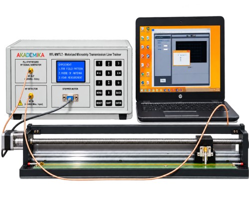
RFL-MMTLT: Motorised Transmission Line Training System
About Product
The RFL-MMTLT is an advanced trainer for studying RF transmission line behavior, enabling precise standing-wave measurement, impedance characterization, Smith chart analysis, and S-parameter evaluation up to 1.5 GHz. Its motorized probe and PC-based interface provide highly accurate visualization of reflections, VSWR, and guided wavelength effects in practical microwave systems.
1) RFL-MMTLT is a new concept to teach the transmission line theory.
2) The kit primarily focuses on Minima and Maxima Measurement for various loads condition as well as various frequencies.
3)Probe/Sensing motion along the transmission line having standard hardening Ball screw arrangement.
4) Analysis of reflection coefficients, VSWR and Impedance for LOAD, OPEN and SHORT termination.
5) Smith Chart Analysis.
1) MICROSTRIP TRANSMISSION LINE
i) Frequency - 250MHz to 1500MHz
ii) Type of device - Passive
iii) Characteristics impedance - 50 Ω
iv) Source Type - PLL Synthesizer
v) Power - +9dBm
vi) Copper thickness - 1oz (35um)
vii) Power handling capacity - +30dBm
viii) Detector Type - Dual Log Type
ix) Output Array Storage - 580 points on self memory
x) Operational Mode - PC & Panel mode
xi) Transmission Line Length - 590mm
xii) Sensing Probe Resolution - 1mm
xiii) Probe Output - dBm / uW/ mV
2) DIRECTIONAL COUPLER
i) Frequency - 20 to 3000 MHZ
ii) Number of port - 3
iii) Result/graph plotting - S11,Z,VSWR
iv) Impedance - 50 Ω
v) Minimum return loss(S11) - -30dB
vi) Power handling - 1W
vii) Temperature Range - 0 to 55
3) Experimental Modes
i) Standing Wave
ii) Transmission Line Parameter
iii) Incident & Reflected Wave
iv) Smith chart
v) S Parameter (S11, S21, S22, S12)
4) Graphs
i) Incident Wave; Reflected Wave, Standing Wave, Smith chart, VSWR, Impedance and S-parameters
ii) Graph comparison facility
5) Software
i) Compatible with Windows 10
6) MICROSTRIP TRANSMISSION LINES
i) Microstrip is a type of electrical transmission line which can be fabricated using printed circuit board technology, and is used to convey microwave-frequency signals. It consists of a conducting strip separated from a ground plane by a dielectric layer known as the substrate. Microwave components such as antennas, couplers, filters, power dividers etc. can be formed from microstrip, with the entire device existing as the pattern of metallization on the substrate. Microstrip is thus much less expensive than traditional waveguide technology, as well as being far lighter and more compact.
MEASUREMENTS WITH MMTLT
1) Standing Wave Pattern
i) Graph shows standing wave characterization graph for OPEN termination condition. An input of 900MHz is given to the Transmission Line we observe 7 harmonics in above graph and 60% power is reflected back to source.
2) Incident Vi and Reflected Vr Power
i) Graph shows the incident and reflected waves of Transmission line. The Yellow line is Incident wave and Red line is reflected wave for short or open terminations. This means that in open or short conditions all the power is reflected back to source.
3) Insertion Loss (S21 or S12)
i) Graph Shows the insertion loss of transmission line is 0.5dB at 350 MHz which means very less power is coupled from port 1 4) S-Parameters (S11 or S22)
i) Graph shows the operating frequency of the Microstrip transmission line is from 270MHz to 1420MHz in which the S11 has values below -10dB through the entire band. S represents 11 how much power is reflected from the port1, and hence is known as the reflection coefficient (sometimes written as gamma: or return loss. If s =0 dB), If S =-10 dB Then 90% power is delivered to the port1 and only 10% is the reflected power from port1.
5) Smith chart
i) Graphs shows the normalized impedance is plotting on smith chart for open termination
6) Open Vs Short Termination Standing wave
i) Graph shows the Standing Wave of the Microstrip Transmission Line with OPEN termination(Yellow)Vs SHORT termination(Blue). It is clearly seen that there is a Phase Shift of 180˚ between the peaks of OPEN and SHORT condition.
7) Standing Wave Pattern for LOAD
i) Graph shows standing wave characterization graph for perfectly matched load condition. An input frequency of 900MHz is given to the Transmission Line we can see that return loss value is -9.6 dB which is closer to -10dB standard value of Return loss
8) Guided Wavelength
i) Graph shows Guided Wavelength at 900MHz frequency with load condition and calculated by any adjacent combination of minima. Graph shown 2ndminima Marker (M1) =91mm and 3rdminima marker (M2) =179mmthen using equation λg =2*(3rd minima-2nd minima) we got guided wavelength is 176mm which is closer to theoretically guide wavelength of 166m at 900MHz frequency.
9) Impedance
i) Graph shows impedance of microstrip transmissionfrom 250MHz to 1500MHz freq range Lineand its show an Impedanceof 59Ohmsat 320MHzandvaries withchange in frequency
DELIVERABLES
i) Transmission line - MODULE assembly - 01nos
ii) Transmission line - Control Unit - 01nos
iii) Directional Coupler - 01nos
iv) SMA(M) to SMA(M) 50 ohm RG316 cable 50cm - 03nos
v) SMA(M) to SMA(M) 50 ohm RG316 cable 50cm - 03nos
vi) Calibration Kit OPEN, SHORT, LOAD - 01nos
vii) 9 pin D type Male to Female cable - 01nos
viii) USB cable (Male A to Male B) - 01no
ix) Power Cord - 01nos
x) Software on Pendrive - 01nos
xi) Manual - 01nos
1) Observation of standing wave pattern at various frequency
2) Analysis of minima and maxima creation at various Frequency
3) Analysis of various load condition on Microstrip transmission line
4) Determination of UNKOWN LOAD Impedance Characterization
5) Determination of unknown frequency characterization using transmission
6) Measurement of S-Parameters for Microstrip Transmission Line
7) Plotting a Normalized Impedance on the Smith Chart
Experiments Using Vector Network Analyzer (VNA)
1) Return Loss & VSWR measurement of Micro strip Transmission Line
2) Impedance Analysis of various loads condition in microstrip transmission line
3) Measurement Reflection coefficient and transmission coefficient of microstrip transmission line
4) Measurement of multiple harmonics in microstrip transmission line
With 35 years of legacy in Technical Education, Akademika extends its expertise to Defence and Skill development, building Innovative, Reliable Training Systems for the next generation of Learners.
Partner with Akademika
Join leading institutions that trust our engineering to Advance Learning and Research.