
Technology Labs
SDR -MIMO : 2x2 MIMO Software Defined Radio
About Product
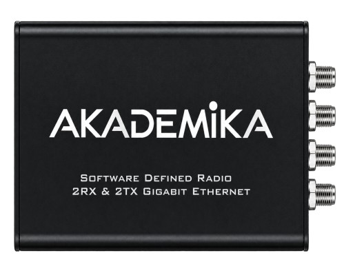
The SDR 2×2 MIMO Trainer is an advanced software-defined radio platform featuring the AD9363 RF transceiver and Xilinx Zynq-7010 SoC. It supports real-time wireless communication experiments, including Alamouti STBC, Zero-Forcing detection, OFDM, and NOMA. The trainer enables hands-on learning in MIMO signal processing, channel estimation, and digital communication using GNU Radio.
1) FPGA-based processing supports real-time implementation of communication algorithms.
2) The reconfigurable platform allows students to modify signal-processing parameters and study concepts like OFDM, MIMO and different detection techniques.
3) External clock synchronization supports coordinated operation with other SDRs in multi-device experiments.
2) The reconfigurable platform allows students to modify signal-processing parameters and study concepts like OFDM, MIMO and different detection techniques.
3) External clock synchronization supports coordinated operation with other SDRs in multi-device experiments.
1) Core Hardware
i) RF Transceiver : AD9363
ii) RF Channels : 2 Tx, 2 Rx with 70MHz-6GHz Freq range
iii) Reference Clock : 40 MHz VCTCXO, 0.5 ppm
iv) SoC : Xilinx Zynq-7010 (XC7Z010)
v) FPGA Resources : ~28K Logic Cells
vi) RAM : 512 MB DDR3 & Flash Memory : 32 MB
vii) USB Interface : USB 2.0 with OTG
ix) Ethernet : Gigabit Ethernet
x) Boot Options : Flash / MicroSD
xi) Power Supply : 5V ± 0.5V, 2A (microUSB)
xii) I/O Logic Level : 1.8V
AD9363 Signal Chain Specifications
i) ADC/DAC Resolution : 12-bit, dual Σ-Δ per channel
ii) Max Sample Rate : 61.44 MSPS(theoretical); ~4–6 MSPS sustained
iii) Channel Bandwidth : 200 kHz – 20 MHz
iv) Tx Outputs : differential (TX1A/B, TX2A/B)
v) Tx Attenuation Range : 90 dB (0.25 dB resolution)
vi) Tx EVM: −34 dB , Tx Noise Floor : −156 dBm/Hz
vii) Tx Monitor : 66 dB dynamic range, 1 dB accuracy
viii) Rx Inputs : differential / single-ended
ix) Rx Noise Figure : 2.5 dB @ 800 MHz, 3.0 dB @ 2.4 GHz
x) Rx Gain Range : Up to 74.5 dB (1 dB steps)
xi) RSSI Dynamic Range : 100 dB
xii) LO Step Size : 2.4 Hz
xiii) BB PLL Range : 700-1400MHz (from 10-80MHz reference)
xiv) FIR Filtering : 128-tap (Tx interpolation / Rx decimation)
xv) Digital I/Q Ports : Two 12-bit parallel ports (P0, P1)
xvi) Signaling Levels : CMOS 1.2–2.5V or LVDS 1.8–2.5V
xvii) Aux ADC : 12-bit / Aux DAC : Two 10-bit
xviii) Package : 144-ball CSP_BGA, 10 mm × 10 mm
3) Zynq-7010 FPGA/SoC Resources
i) Processor : Dual-core ARM Cortex-A9, up to 667 MHz
ii) L1 Cache : 32 KB instruction + 32 KB data per core
iii) L2 Cache : 512 KB
iv) On-Chip Memory : 256 KB
v) DMA Channels : 8 (4 dedicated to PL)
vi) Logic Slices : 4,400
vii) 6-input LUTs : 17,600
viii) Flip-Flops : 35,200
ix) Block RAM : 2.1 Mb
x) DSP Slices : 80 (DSP48E1) , XADC : Dual-channel, 12-bit
4) Required Software Stack
i) libiio - the core driver/communication library Pluto uses
ii) libad9361-iio - helper library for the AD9361/AD9363
iii) GNU Radio (3.10.x with Python 3)
8) Computer Requirements
i) Processor : Multi-core CPU with RAM 8GB Minimum
ii) USB 3.0 host ports and dedicated 5V/2A for Pluto+Linux/Ubuntu for stable GNU Radio and SDR operation
i) RF Transceiver : AD9363
ii) RF Channels : 2 Tx, 2 Rx with 70MHz-6GHz Freq range
iii) Reference Clock : 40 MHz VCTCXO, 0.5 ppm
iv) SoC : Xilinx Zynq-7010 (XC7Z010)
v) FPGA Resources : ~28K Logic Cells
vi) RAM : 512 MB DDR3 & Flash Memory : 32 MB
vii) USB Interface : USB 2.0 with OTG
ix) Ethernet : Gigabit Ethernet
x) Boot Options : Flash / MicroSD
xi) Power Supply : 5V ± 0.5V, 2A (microUSB)
xii) I/O Logic Level : 1.8V
AD9363 Signal Chain Specifications
i) ADC/DAC Resolution : 12-bit, dual Σ-Δ per channel
ii) Max Sample Rate : 61.44 MSPS(theoretical); ~4–6 MSPS sustained
iii) Channel Bandwidth : 200 kHz – 20 MHz
iv) Tx Outputs : differential (TX1A/B, TX2A/B)
v) Tx Attenuation Range : 90 dB (0.25 dB resolution)
vi) Tx EVM: −34 dB , Tx Noise Floor : −156 dBm/Hz
vii) Tx Monitor : 66 dB dynamic range, 1 dB accuracy
viii) Rx Inputs : differential / single-ended
ix) Rx Noise Figure : 2.5 dB @ 800 MHz, 3.0 dB @ 2.4 GHz
x) Rx Gain Range : Up to 74.5 dB (1 dB steps)
xi) RSSI Dynamic Range : 100 dB
xii) LO Step Size : 2.4 Hz
xiii) BB PLL Range : 700-1400MHz (from 10-80MHz reference)
xiv) FIR Filtering : 128-tap (Tx interpolation / Rx decimation)
xv) Digital I/Q Ports : Two 12-bit parallel ports (P0, P1)
xvi) Signaling Levels : CMOS 1.2–2.5V or LVDS 1.8–2.5V
xvii) Aux ADC : 12-bit / Aux DAC : Two 10-bit
xviii) Package : 144-ball CSP_BGA, 10 mm × 10 mm
3) Zynq-7010 FPGA/SoC Resources
i) Processor : Dual-core ARM Cortex-A9, up to 667 MHz
ii) L1 Cache : 32 KB instruction + 32 KB data per core
iii) L2 Cache : 512 KB
iv) On-Chip Memory : 256 KB
v) DMA Channels : 8 (4 dedicated to PL)
vi) Logic Slices : 4,400
vii) 6-input LUTs : 17,600
viii) Flip-Flops : 35,200
ix) Block RAM : 2.1 Mb
x) DSP Slices : 80 (DSP48E1) , XADC : Dual-channel, 12-bit
4) Required Software Stack
i) libiio - the core driver/communication library Pluto uses
ii) libad9361-iio - helper library for the AD9361/AD9363
iii) GNU Radio (3.10.x with Python 3)
8) Computer Requirements
i) Processor : Multi-core CPU with RAM 8GB Minimum
ii) USB 3.0 host ports and dedicated 5V/2A for Pluto+Linux/Ubuntu for stable GNU Radio and SDR operation
1) To study and verify the Alamouti STBC scheme for a 2×2 MIMO system.
2) To study 2×2 MIMO spatial multiplexing with 16-QAM using Zero-Forcing (ZF) detection.
3) To study V-BLAST SIC for successive detection of two 16-QAM streams.
4) To study 2×2 MIMO using Maximum Likelihood (ML) detection for QPSK signals.
5) To study SVD across MIMO
6) To estimate channel matrix and calculate channel capacity
7) To Study and Implement MIMO OFDM.
8) To Study Waterfilling Power Allocation and NOMA.
9) And many more based on the capacity of the hardware
2) To study 2×2 MIMO spatial multiplexing with 16-QAM using Zero-Forcing (ZF) detection.
3) To study V-BLAST SIC for successive detection of two 16-QAM streams.
4) To study 2×2 MIMO using Maximum Likelihood (ML) detection for QPSK signals.
5) To study SVD across MIMO
6) To estimate channel matrix and calculate channel capacity
7) To Study and Implement MIMO OFDM.
8) To Study Waterfilling Power Allocation and NOMA.
9) And many more based on the capacity of the hardware
With 35 years of legacy in Technical Education, Akademika extends its expertise to Defence and Skill development, building Innovative, Reliable Training Systems for the next generation of Learners.
Partner with Akademika
Join leading institutions that trust our engineering to Advance Learning and Research.