Technology Labs
WL-IOT: Universal IoT Training system
About Product
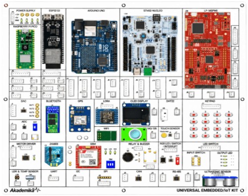
The WL-IOT Universal IoT Training System is a comprehensive platform designed for hands-on learning of IoT, embedded systems, and wireless communication technologies. It supports Arduino, ESP32, Raspberry Pi, STM32, and MSP microcontrollers with various sensors, actuators, and wireless modules. The trainer enables practical experiments in smart automation, sensor interfacing, data communication, and cloud-based IoT applications.
1) The UNIVERSAL IOT TRAINER KIT is a single training and development platform that brings together five popular microcontroller families — Arduino UNO,ESP32, STM32 Nucleo, Raspberry Pi Pico w2, and MSP Board. It integrates 20+ ready-to-use sections covering sensors, displays, actuators, analog interfaces, Motor Driver and both wired (UART, I2C, SPI, CAN) and wireless (Wi-Fi, Bluetooth, ZigBee, GSM, GPS) communication modules. This lets students and developers learn the same Emmbedded concept across different controller architectures without rewiring hardware for each one. From basic GPIO experiments to advanced IoT and multi-controller applications, it's built for structured teaching labs, workshops, and rapid prototyping alike.
THE UNIVERSAL IOT TRAINER KIT
i) Five Microcontrollers Arduino Development Board, ESP32 Development Board , STM32 Nucleo, Raspberry Pi Pico w2, and MSP Board.
ii) The Dimension Of Board 320mm x 280mm.
iii) Carrier board Includes sensors, displays, actuators, analog interfaces, Motor Driver.
iv) Communication Protocols UART, I2C, SPI, CAN
vWireless Module Wi-Fi, Bluetooth, ZigBee, GSM, GPS.
vi) External Sensor Interface Analog Sensor, One Wire Sensor , PWM Sensor, GPIO Sensor.
vii) SOFTWARE for program the Hardware.
viii) OLED Display for Display the Message.
ix) Power Supply : 12V , 5V for powering On board.
Microcontroller Specifications
1) ARDUINO Development Modules
i) 48 MHz Arm® Cortex®-M4 microprocessor with a floating point unit (FPU)
ii) 256 kB Flash Memory
iii) 32 kB SRAM
iv) 8 kB Data Memory (EEPROM)
v) 5 V operating voltage
2) ESP32 Development Modules
i) Processor: 32-bit Xtensa LX7 Dual-Core, Up to 240MHz
ii) Wireless Connectivity: Wi-Fi IEEE 802.11 b/g/n 2.4GHz + Bluetooth 5 (BLE)
iii) Flash Memory: 8MB Quad SPI Flash
iv) PSRAM: 8MB Octal SPI PSRAM
v) Module: ESP32-S3-WROOM-1U-N8R8
vi) Power Supply: 5V DC
3) STM32 NUCLEO Modules
i) STM32G431RB Cortex-M4F @ 170 MHz
ii) 128 KB Flash, ~32 KB total SRAM resources
iii) High-performance ADCs
iv) UART, SPI, I2C, CAN-FDFPU + DSP instructions
4) RASPBERRY PI PICO 2 W Modules
i) Microcontroller: RP2350 (Selectable Dual ARM Cortex-M33 or Dual Hazard3 RISC-V)
ii) Clock Speed: 150 MHz
iii) Memory: 520 KB SRAM, 4 MB QSPI Flash
iv) Wireless: Onboard 2.4 GHz Wi-Fi + Bluetooth 5.2 / BLE
v) Peripherals: 12 Programmable I/O (PIO) state machines, Arm TrustZone security
5) MSP Development Modules
i) ARM Cortex-M0+ @ 80 MHz
ii) 128 KB Flash,32 KB SRAM
iii) Up to 60 GPIO, 4xUART, 2xSPI, 2xI2C,CAN-FD
iv) 2x12-bit 4-MSPS ADC,12-bit DAC
v) 2xOp-Amps + 3xComparators
vi) DMA, AES, CRC, TRNG
6) Raspberry Pi IoT Gateway ( Optional )
i) Raspberry Pi based mainboard with Ethernet, HDMI, USB, RS485/RS232, Micro SD and expansion interfaces, supporting wired and wireless IoT gateway applications.
WIRELESS MODULES
i) Bluetooth : Provides short-range wireless communication with mobile phones, PCs, and other devices.
ii) Zigbee : Provides low-power wireless communication for sensor networks and automation systems.
iii) GSM : Provides cellular communication for SMS, calls, data transfer, and remote monitoring.
iv) Wifi : Provides wireless network and Internet connectivity for IoT and data communication.
v) GPS : To read data from a GPS receiver.
vi) LORA : Provides long-range, low-power wireless communication for remote sensor and IoT applications.
Carrier Board Specifications
i) DAC (DAC124S085CIMM_NOPB) : Resolution: 12-bit , Channels: 4-channel quad
ii) DACADC(ADS7946SRTER) : Resolution: 14-bit, Channels: 2-channel, 10K POT
iii) DRV8833PWPR (motor driver) : H-Bridges: 2, Output Current: 1.5A
iv) LDR & LM35 : Type: Light Dependent Resistor (LDR) Type: Precision Centigrade Temperature Sensor (LM35)
v) CAN (SN65HVD230DR) :Data Rate: 1 Mbps, Supply Voltage: 3.3 V
vi) RS-485(SP3485CN): Data Rate: 10 Mbps, Supply Voltage: 3.3 V
vii) Relay: 5V Coil, 10A Switching Capacity
viii) Buzzer: 5V Operating Voltage
ix) RGB led : Configuration: Common Cathode, Package: 5mm Diffused
x) Temparature Sensor : Temp Range: -40°C to 80°C , Humidity Range: 0-100% RH
xi) 4 dip switch,
xii) 4 output led
xiii) Keypad(switch) 4x4, Layout: 4x4 Matrix, 16Keys
xiv) Mux-demux for : uart selection
xv) Power Supply : 12V , 5V
Carrier Board Modules
i) Gas Sensor : to study air quality monitoring and hazardous gas concentration detection.
ii) Ultrasonic Sensor : Distance Measurement.
iii) OLED Display: Size: Display Parameters Interface: I2C
External Sensor Interface
i) Analog Sensor
ii) One Wire Sensor
iii) WM Sensor
iv) GPIO Sensor
Extra Communication Buses (Port) Specifications
i) I2C based Sensors or Module Connect to I2C Bus
ii) SPI based Sensors or Module Connect to SPI Bus
iii) UART based Sensors or Module Connect to UART Bus
iv) CAN Transceiver : (SN65HVD230DR) compatible
v) CAN bus transceiver with built-in ESD protection
vi) RS485 Transceiver : MODUBUS Implementation.
SOFTWAR
1) ARDUINO IDE
ARDUINO IDE the official, open-source software used to write, compile, and upload code
2) STM32 CUBE MX
A visual configuration tool. It helps you design your project before you start writing code.
3) STM32 CUBE IDE
A complete C/C++ development environment for STM32 microcontrollers.
4) Thonny
Lightweight Python IDE designed specifically for beginners and physical computing.
5) Code composer studio
i) Code Composer Studio is a highly professional, industrial-grade IDE based on the Eclipse framework. It is used exclusively for Texas Instruments (TI) embedded processors.
ii) Micro-Python Programming (Arduino Labs for Micro python)
6) Block Code
i) Block Programming SOFTWARE.
ii) Circuit design : Cloud-Based software for IoT Circuit Designing and Validation Cloud-based software for IOT Simulation Software.
iii) Visualization : For Data storage, analysis, and remoteaccess. It should support the students to create new IoT applications
iv)Cloud Database Storage. (Optional)
With 35 years of legacy in Technical Education, Akademika extends its expertise to Defence and Skill development, building Innovative, Reliable Training Systems for the next generation of Learners.
Partner with Akademika
Join leading institutions that trust our engineering to Advance Learning and Research.